
در آموزش های قبلی راه اندازی ماژول MPU650 شرح داده شد . در این آموزش قصد داریم به راه اندازی ماژول MPU9250 بپردازیم . MPU9250 یک سنسور MEMS یکپارچه می باشد که شامل چندین واحد در قالب یک چیپ است . این سنسور قابلیت اندازه گیری شتاب ، زاویه ژایرو و میدان مغناطیسی را در سه جهت محور مختصات دارد لذا یک سنسور 9 محوره است . بر خلاف MPU6050 این سنسور پایداری بسیار بیشتری دارد همچنین قیمت آن چند برابر MPU6050 است . از این سنسور می توان در شرایطی که نیاز به حساسیت بالا و پایداری وجود دارد استفاده نمود . MPU9250 می تواند مقادیر زاویه ژیرو را تا 2000 زاویه در ثانیه اندازه گیری کند . همچنین می تواند شتاب را در چهار بازه 2g ، 4g ، 8g و 16g اندازه گیری کند . ماژول mpu9250 را به راحتی می توانید جایگزین ماژول های MPU6050 و MPU6515 کنید . رابط ارتباطی این سنسور I2C و SPI است همچنین دارای وقفه خارجی قابل برنامه ریزی می باشد که می توانید از آن برای تشخیص حرکت های ناگهانی ، تشخیص سقوط آزاد و… استفاده کنید .
پین های ماژول MPU9250 :
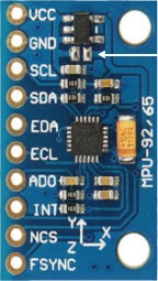
پین های VCC و GND به ترتیب تغذیه و زمین ماژول می باشند .
SDA و SCL پین های ارتباط I2C ماژول هستند .
EDA و ECL نقش پین های SDA و SCL را دارند که برای اتصال ماژول های دیگر به این ماژول استفاده می شود (پین های کمکی I2C )
ADO برای انتخاب آدرس در ارتباط I2C و نیز پین SDO در ارتباط SPI می باشد .
NCS پین انتخاب مازول در ارتباط SPI است .
FSYNC پین همگام سازی داده های خروجی .
کد های آردوینو :
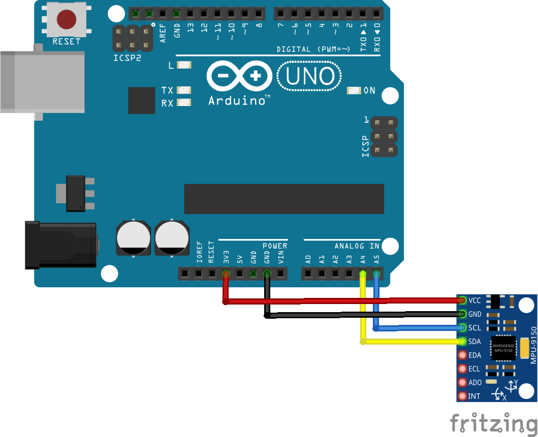
ابتدا ماژول MPU9250 را مانند تصویر زیر به آردوینو متصل کرده و سپس کد های زیر را بر روی برد آپلود کنید :
#include <Wire.h>
#include <TimerOne.h>

#define MPU9250_ADDRESS 0x68
#define MAG_ADDRESS 0x0C

#define GYRO_FULL_SCALE_250_DPS 0x00
#define GYRO_FULL_SCALE_500_DPS 0x08
#define GYRO_FULL_SCALE_1000_DPS 0x10
#define GYRO_FULL_SCALE_2000_DPS 0x18

#define ACC_FULL_SCALE_2_G 0x00
#define ACC_FULL_SCALE_4_G 0x08
#define ACC_FULL_SCALE_8_G 0x10
#define ACC_FULL_SCALE_16_G 0x18

// This function read Nbytes bytes from I2C device at address Address.
// Put read bytes starting at register Register in the Data array.
void I2Cread(uint8_t Address, uint8_t Register, uint8_t Nbytes, uint8_t* Data)
{
// Set register address
Wire.beginTransmission(Address);
Wire.write(Register);
Wire.endTransmission();

// Read Nbytes
Wire.requestFrom(Address, Nbytes);
uint8_t index=0;
while (Wire.available())
Data[index++]=Wire.read();
}


// Write a byte (Data) in device (Address) at register (Register)
void I2CwriteByte(uint8_t Address, uint8_t Register, uint8_t Data)
{
// Set register address
Wire.beginTransmission(Address);
Wire.write(Register);
Wire.write(Data);
Wire.endTransmission();
}

// Initial time
long int ti;
volatile bool intFlag=false;

// Initializations
void setup()
{
// Arduino initializations
Wire.begin();
Serial.begin(115200);

// Set accelerometers low pass filter at 5Hz
I2CwriteByte(MPU9250_ADDRESS,29,0x06);
// Set gyroscope low pass filter at 5Hz
I2CwriteByte(MPU9250_ADDRESS,26,0x06);


// Configure gyroscope range
I2CwriteByte(MPU9250_ADDRESS,27,GYRO_FULL_SCALE_1000_DPS);
// Configure accelerometers range
I2CwriteByte(MPU9250_ADDRESS,28,ACC_FULL_SCALE_4_G);
// Set by pass mode for the magnetometers
I2CwriteByte(MPU9250_ADDRESS,0x37,0x02);

// Request continuous magnetometer measurements in 16 bits
I2CwriteByte(MAG_ADDRESS,0x0A,0x16);

pinMode(13, OUTPUT);
Timer1.initialize(10000); // initialize timer1, and set a 1/2 second period
Timer1.attachInterrupt(callback); // attaches callback() as a timer overflow interrupt


// Store initial time
ti=millis();
}

// Counter
long int cpt=0;

void callback()
{
intFlag=true;
digitalWrite(13, digitalRead(13) ^ 1);
}

// Main loop, read and display data
void loop()
{
while (!intFlag);
intFlag=false;

// Display time
Serial.print (millis()-ti,DEC);
Serial.print ("\t");


// _______________
// ::: Counter :::

// Display data counter
// Serial.print (cpt++,DEC);
// Serial.print ("\t");


// ____________________________________
// ::: accelerometer and gyroscope :::

// Read accelerometer and gyroscope
uint8_t Buf[14];
I2Cread(MPU9250_ADDRESS,0x3B,14,Buf);

// Create 16 bits values from 8 bits data

// Accelerometer
int16_t ax=-(Buf[0]<<8 | Buf[1]);
int16_t ay=-(Buf[2]<<8 | Buf[3]);
int16_t az=Buf[4]<<8 | Buf[5];

// Gyroscope
int16_t gx=-(Buf[8]<<8 | Buf[9]);
int16_t gy=-(Buf[10]<<8 | Buf[11]);
int16_t gz=Buf[12]<<8 | Buf[13];

// Display values

// Accelerometer
Serial.print (ax,DEC);
Serial.print ("\t");
Serial.print (ay,DEC);
Serial.print ("\t");
Serial.print (az,DEC);
Serial.print ("\t");

// Gyroscope
Serial.print (gx,DEC);
Serial.print ("\t");
Serial.print (gy,DEC);
Serial.print ("\t");
Serial.print (gz,DEC);
Serial.print ("\t");


// _____________________
// ::: Magnetometer :::


// Read register Status 1 and wait for the DRDY: Data Ready

uint8_t ST1;
do
{
I2Cread(MAG_ADDRESS,0x02,1,&ST1);
}
while (!(ST1&0x01));

// Read magnetometer data
uint8_t Mag[7];
I2Cread(MAG_ADDRESS,0x03,7,Mag);

// Create 16 bits values from 8 bits data

// Magnetometer
int16_t mx=-(Mag[3]<<8 | Mag[2]);
int16_t my=-(Mag[1]<<8 | Mag[0]);
int16_t mz=-(Mag[5]<<8 | Mag[4]);


// Magnetometer
Serial.print (mx+200,DEC);
Serial.print ("\t");
Serial.print (my-70,DEC);
Serial.print ("\t");
Serial.print (mz-700,DEC);
Serial.print ("\t");


// End of line
Serial.println("");
// delay(100);
}
سلام
بنده تمام مراحل فوق رو انجام دادم ولی سنسور داده ای ثبت نمیکنه لطفا راهنمایی کنید باید چه کار کنم ممنون