
MPU6050 یک سنسور ژیروسکوپ و شتاب سنج سه محور می باشد .این سنسور مقادیر شتاب و زاویه ژیرو رو در سه محور x ، y و z به دست می دهد ( در واقع شش محوره می باشد ) . یکی از مزیت های مهم این سنسور قیمت بسیار پایین و دقت بالای آن است . MPU6050 یک سنسور MEMS می باشد در واقع در داخل چیپ MPU6050 مکانیزم های الکترومکانیکی میکرومتری دارد . این سنسور قایلیت اندازه گیری زاویه را با سرعت های 250±، 500±، 1000± و 2000± درجه در ثانیه و نیز قابلیت اندازه گیری شتاب با دقت های 2g، ±4g، ±8g، ±16g± را دارد . علاوه بر آن MPU6050 دارای 1 کیلوبایت حافظه FIFO داخلی است که امکان ذخیره داده ها را در زمانی که MCU قادر به خواندن داده نیست فراهم می سازد . به راحتی با استفاده از مقادیر رجیستری ها و همچنین فلوچارت های دیتاشیت این ماژول ، می توانید ماژول را با استفاده از کتابخانه Wire آردوینو راه اندازی کنید . بر روی برد ماژول MPU6050 رگولاتور 3.3 ولتی قرار داده شده است که امکان اتصال ماژول به 5 ولت را فراهم می سازد. از MPU6050 در پروژه های مختلفی می توان استفاده نمود از پهباد ها تا لرزه نگار .
در شکل زیر پایه های ماژول MPU6050 نشان داده شده است :
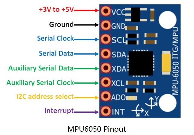
- Vcc پایه تغذیه ماژول می باشد
- GND پین زمین ماژول
- SDA و SCL پین های ارتباط I2C ماژول می باشند
- XDA پین SDA ارتباط I2C در حالت Master ( جهت اتصال سنسور های دیگر)
- XCL پین SCL ارتباط I2C در حالت Master ( جهت اتصال سنسور های دیگر )
نکته جالب راجب به این ماژول این است که این ماژول قابلیت ارتباط I2C به صورت Master را نیز دارد که امکان اتصال سنسور هایی دیگری همچون قطب نما را فراهم می سازد .
پین ها ماژول را مطابق شکل زیر به برد آردوینوی خود متصل نمایید :
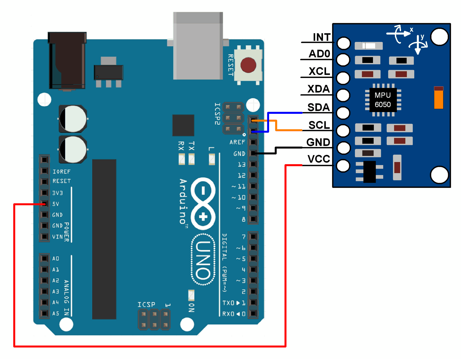
کد های زیر را بر روی برد خود آپلود کنید :
include <Wire.h>
const int MPU = 0x68; // MPU6050 I2C address
float AccX, AccY, AccZ;
float GyroX, GyroY, GyroZ;
float accAngleX, accAngleY, gyroAngleX, gyroAngleY, gyroAngleZ;
float roll, pitch, yaw;
float AccErrorX, AccErrorY, GyroErrorX, GyroErrorY, GyroErrorZ;
float elapsedTime, currentTime, previousTime;
int c = 0;
void setup() {
  Serial.begin(19200);
  Wire.begin();                      // Initialize comunication
  Wire.beginTransmission(MPU);       // Start communication with MPU6050 // MPU=0x68
  Wire.write(0x6B);                  // Talk to the register 6B
  Wire.write(0x00);                  // Make reset - place a 0 into the 6B register
  Wire.endTransmission(true);        //end the transmission
  /*
  // Configure Accelerometer Sensitivity - Full Scale Range (default +/- 2g)
  Wire.beginTransmission(MPU);
  Wire.write(0x1C);                  //Talk to the ACCEL_CONFIG register (1C hex)
  Wire.write(0x10);                  //Set the register bits as 00010000 (+/- 8g full scale range)
  Wire.endTransmission(true);
  // Configure Gyro Sensitivity - Full Scale Range (default +/- 250deg/s)
  Wire.beginTransmission(MPU);
  Wire.write(0x1B);                   // Talk to the GYRO_CONFIG register (1B hex)
  Wire.write(0x10);                   // Set the register bits as 00010000 (1000deg/s full scale)
  Wire.endTransmission(true);
  delay(20);
  */
  // Call this function if you need to get the IMU error values for your module
  calculate_IMU_error();
  delay(20);
}
void loop() {
  // === Read acceleromter data === //
  Wire.beginTransmission(MPU);
  Wire.write(0x3B); // Start with register 0x3B (ACCEL_XOUT_H)
  Wire.endTransmission(false);
  Wire.requestFrom(MPU, 6, true); // Read 6 registers total, each axis value is stored in 2 registers
  //For a range of +-2g, we need to divide the raw values by 16384, according to the datasheet
  AccX = (Wire.read() << 8 | Wire.read()) / 16384.0; // X-axis value
  AccY = (Wire.read() << 8 | Wire.read()) / 16384.0; // Y-axis value
  AccZ = (Wire.read() << 8 | Wire.read()) / 16384.0; // Z-axis value
  // Calculating Roll and Pitch from the accelerometer data
  accAngleX = (atan(AccY / sqrt(pow(AccX, 2) + pow(AccZ, 2))) * 180 / PI) - 0.58; // AccErrorX ~(0.58) See the calculate_IMU_error()custom function for more details
  accAngleY = (atan(-1 * AccX / sqrt(pow(AccY, 2) + pow(AccZ, 2))) * 180 / PI) + 1.58; // AccErrorY ~(-1.58)
  // === Read gyroscope data === //
  previousTime = currentTime;        // Previous time is stored before the actual time read
  currentTime = millis();            // Current time actual time read
  elapsedTime = (currentTime - previousTime) / 1000; // Divide by 1000 to get seconds
  Wire.beginTransmission(MPU);
  Wire.write(0x43); // Gyro data first register address 0x43
  Wire.endTransmission(false);
  Wire.requestFrom(MPU, 6, true); // Read 4 registers total, each axis value is stored in 2 registers
  GyroX = (Wire.read() << 8 | Wire.read()) / 131.0; // For a 250deg/s range we have to divide first the raw value by 131.0, according to the datasheet
  GyroY = (Wire.read() << 8 | Wire.read()) / 131.0;
  GyroZ = (Wire.read() << 8 | Wire.read()) / 131.0;
  // Correct the outputs with the calculated error values
  GyroX = GyroX + 0.56; // GyroErrorX ~(-0.56)
  GyroY = GyroY - 2; // GyroErrorY ~(2)
  GyroZ = GyroZ + 0.79; // GyroErrorZ ~ (-0.8)
  // Currently the raw values are in degrees per seconds, deg/s, so we need to multiply by sendonds (s) to get the angle in degrees
  gyroAngleX = gyroAngleX + GyroX * elapsedTime; // deg/s * s = deg
  gyroAngleY = gyroAngleY + GyroY * elapsedTime;
  yaw =  yaw + GyroZ * elapsedTime;
  // Complementary filter - combine acceleromter and gyro angle values
  roll = 0.96 * gyroAngleX + 0.04 * accAngleX;
  pitch = 0.96 * gyroAngleY + 0.04 * accAngleY;

  // Print the values on the serial monitor
  Serial.print(roll);
  Serial.print("/");
  Serial.print(pitch);
  Serial.print("/");
  Serial.println(yaw);
}
void calculate_IMU_error() {
  // We can call this funtion in the setup section to calculate the accelerometer and gyro data error. From here we will get the error values used in the above equations printed on the Serial Monitor.
  // Note that we should place the IMU flat in order to get the proper values, so that we then can the correct values
  // Read accelerometer values 200 times
  while (c < 200) {
    Wire.beginTransmission(MPU);
    Wire.write(0x3B);
    Wire.endTransmission(false);
    Wire.requestFrom(MPU, 6, true);
    AccX = (Wire.read() << 8 | Wire.read()) / 16384.0 ;
    AccY = (Wire.read() << 8 | Wire.read()) / 16384.0 ;
    AccZ = (Wire.read() << 8 | Wire.read()) / 16384.0 ;
    // Sum all readings
    AccErrorX = AccErrorX + ((atan((AccY) / sqrt(pow((AccX), 2) + pow((AccZ), 2))) * 180 / PI));
    AccErrorY = AccErrorY + ((atan(-1 * (AccX) / sqrt(pow((AccY), 2) + pow((AccZ), 2))) * 180 / PI));
    c++;
  }
  //Divide the sum by 200 to get the error value
  AccErrorX = AccErrorX / 200;
  AccErrorY = AccErrorY / 200;
  c = 0;
  // Read gyro values 200 times
  while (c < 200) {
    Wire.beginTransmission(MPU);
    Wire.write(0x43);
    Wire.endTransmission(false);
    Wire.requestFrom(MPU, 6, true);
    GyroX = Wire.read() << 8 | Wire.read();
    GyroY = Wire.read() << 8 | Wire.read();
    GyroZ = Wire.read() << 8 | Wire.read();
    // Sum all readings
    GyroErrorX = GyroErrorX + (GyroX / 131.0);
    GyroErrorY = GyroErrorY + (GyroY / 131.0);
    GyroErrorZ = GyroErrorZ + (GyroZ / 131.0);
    c++;
  }
  //Divide the sum by 200 to get the error value
  GyroErrorX = GyroErrorX / 200;
  GyroErrorY = GyroErrorY / 200;
  GyroErrorZ = GyroErrorZ / 200;
  // Print the error values on the Serial Monitor
  Serial.print("AccErrorX: ");
  Serial.println(AccErrorX);
  Serial.print("AccErrorY: ");
  Serial.println(AccErrorY);
  Serial.print("GyroErrorX: ");
  Serial.println(GyroErrorX);
  Serial.print("GyroErrorY: ");
  Serial.println(GyroErrorY);
  Serial.print("GyroErrorZ: ");
  Serial.println(GyroErrorZ);
}
پس از اتصال ماژول به آردوینو و پروگرام کردن آردوینو ، وارد محیط Serial monitor آردوینو IDEشوید .