
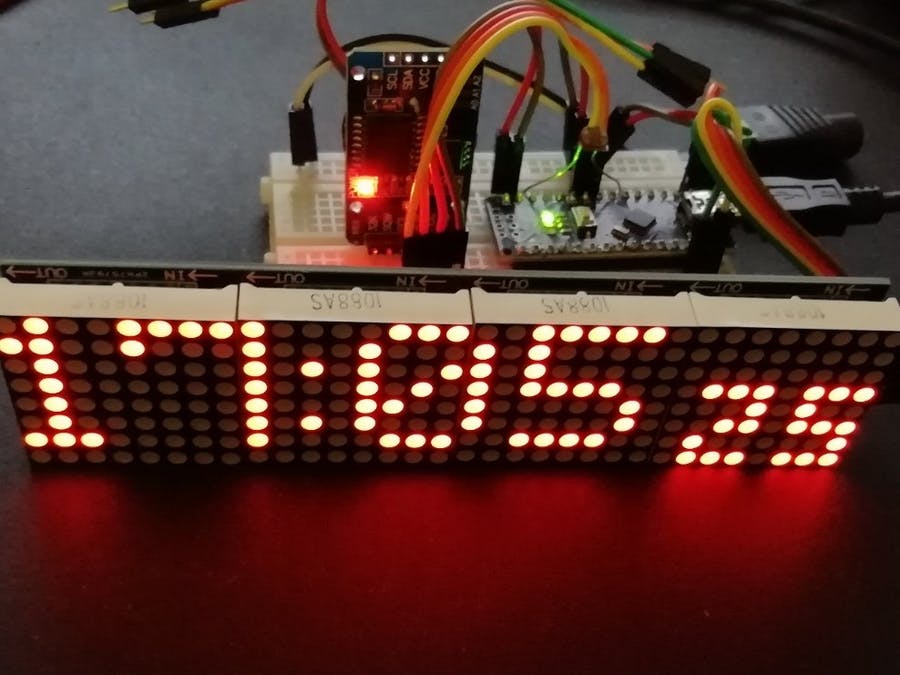
در این پروژه از یک ماژول MAX7219 و همچنین ماژول DS3231 برای ساخت یک تابلو روان با قابلیت نمایش ساعت و دما استفاده می کنیم . برای نمایش ساعت و دما و… در اماکن بزرگ که افراد فاصله زیادی تا نمایشگر دارند ، استفاده از سونسگمنت های معمولی کار ساز نیست .لذا در چنین مواردی از سون سگمنت های بزرگ استفاده می کنند . سون سگمنت های بزرگ معمولا قیمت بالایی دارند و نیز تنها قادر به نمایش اعداد و تعادی حروف هستند . در چنین شرایطی استفاده از تابلو روان ها بسیار مقرون به صرف تر است . علاوه بر آن تابلو روان ها قابلیت نمایش حروف را نیز دارند . در این پروژه از یک ماژول MAX7219 با ابعاد 32*8 برای نمایش زمان و دما استفاده شده است . همچنین از ماژول DS3231 برای شمارش زمان و اندازه گیری دما استفاده می شود . برای کنترل شدت نور نیز یک فوتوسل به یکی از پایه های ADC آردوینو متصل گردید. زیر شماتیک پروژه می باشد :
همان طور که در شماتیک فوق مشخص است از یک فوتوسل جهت کنترل شدت نور ماژول MAX7219 استفاده شده است .
برنامه آردوینو :
/*  Arduino Nano DS3231 clock with LED Matrix 4x(8x8) SPI
 *
 *  Arduino Nano 5V logic - 32kB prog. space
*  Tools:Board: Arduino Nano; Processor: ATmega328P (Old Bootloader)!!
*  LED Matrix 4x(8x8) SPI with connector on the right side (last module)
*  https://www.banggood.com/MAX7219-Dot-Matrix-Module-4-in-1-Display-For-Arduino-p-1072083.html?rmmds=myorder&cur_warehouse=CN
*
*  CONNECTIONS:
*  >> LCD 4x64   -> Arduino Nano: (using Hardware SPI):
*       5V            -> 5V pin
*       GND           -> GND pin
*     CLK_PIN        ->  13  // or SCK
*    DATA_PIN        ->  11  // or MOSI
*      CS_PIN        ->  10  // or SS
*
*  >> DS3231 RTC -> Arduino Nano:
*       SDA (DAT)     -> A4
*       SCL (CLK)     -> A5
* Inspired by : 1) Arduino Clock by AnthoTRONICS Last edit: March 22,2019
* but without MD_parola because of its large footprint! New getdate function.
* 2) Simplest UNO Digital Clock Ever by plouc68000:
* https://create.arduino.cc/projecthub/plouc68000/simplest-uno-digital-clock-ever-4613aa?ref=user&ref_id=680368&offset=1
* 3) LEDDotMatrixClock.ino by Leonardo Sposina, but here without "Max72xxPanel.h"
* https://github.com/leonardosposina/arduino-led-dot-matrix-clock/blob/master/LEDDotMatrixClock/LEDDotMatrixClock.ino
* Not using Max72xxPanel.h, but small size digits are stll used. Small footprint code here.
* Replace in library MD_MAX72XX/src/MD_MAX72xx_font.cpp :
* 1)  #define USE_NEW_FONT 1
* 2)  fonts #148 ... 158 must be replaced with 3x5 fonts:
  3, 248, 136, 248,   // 48 0
  3, 144, 248, 128,   // 49 1
  3, 200, 168, 184,   // 50 2
  3, 136, 168, 248,   // 51 3
  3, 112, 72, 224,    // 52 4
  3, 184, 168, 232,   // 53 5
  3, 248, 168, 232,   // 54 6
  3, 8, 232, 24,      // 55 7
  3, 248, 168, 248,   // 56 8
  3, 184, 168, 248,   // 57 9
  1, 80,              // 58 :
*
* project: 13790 bytes (44%); variables 361 bytes (17%)
* Author: MVP https://www.hackster.io/M-V-P
*/

#include <SPI.h>
#include "DS3231.h"
#include "MD_MAX72xx_lib.h"
//#include "Font_Data.h"

DS3231 rtc(SDA, SCL);     // Real time clock

const byte LDR_PIN = A2; // LDR Sensor pin

#define MAX_DEVICES  4
// Define pins
#define CLK_PIN   13  // or SCK
#define DATA_PIN  11  // or MOSI
#define CS_PIN    10  // or SS
#define HARDWARE_TYPE MD_MAX72XX::ICSTATION_HW

#define USE_NEW_FONT 1

#define BUF_SIZE      20  // text buffer size
#define CHAR_SPACING  1   // pixels between characters

char buf[BUF_SIZE], secs[4];
uint8_t dots;


// SPI hardware interface
// Max72xxPanel matrix = Max72xxPanel(CS_PIN, H_DISPLAYS, V_DISPLAYS);
MD_MAX72XX matrix = MD_MAX72XX(HARDWARE_TYPE, CS_PIN, MAX_DEVICES);

const byte WAIT = 100;
const byte SPACER = 1;
byte FONT_WIDTH;

bool timeset=false;

void adjustClock(String data) {
  byte _day = data.substring(0,2).toInt();
  byte _month = data.substring(3,5).toInt();
  int _year = data.substring(6,10).toInt();
  byte _hour = data.substring(11,13).toInt();
  byte _min = data.substring(14,16).toInt();
  byte _sec = data.substring(17,19).toInt();
  rtc.setTime(_hour, _min, _sec);
  rtc.setDate(_day, _month, _year);
  Serial.println(F(">> Datetime successfully set!"));
  timeset=true;
}

byte ledintensitySelect(int light) {
  byte _value = 0;
  if (light >= 0 && light <= 127) {
    _value = 12;
  } else if (light >= 128 && light <= 319) {
    _value = 3;
  } else if (light >= 320 && light <= 512) {
    _value = 0;
  }
  return _value;
};


void printText(uint8_t modStart, uint8_t modEnd, char *pMsg)
// Print the text string to the LED matrix modules specified.
// Message area is padded with blank columns after printing.
{
  uint8_t   state = 0;
  uint8_t   curLen;
  uint16_t  showLen;
  uint8_t   cBuf[FONT_WIDTH];
  int16_t   col = ((modEnd + 1) * COL_SIZE) - 1;

  matrix.control(modStart, modEnd, MD_MAX72XX::UPDATE, MD_MAX72XX::OFF);

  do     // finite state machine to print the characters in the space available
  {
    switch(state)
    {
      case 0: // Load the next character from the font table
        // if we reached end of message, reset the message pointer
        if (*pMsg == '\0')
        {
          showLen = col - (modEnd * COL_SIZE);  // padding characters
          state = 2;
          break;
        }

        // retrieve the next character form the font file
        showLen = matrix.getChar(*pMsg++, sizeof(cBuf)/sizeof(cBuf[0]), cBuf);
        curLen = 0;
        state++;
        // !! deliberately fall through to next state to start displaying

      case 1: // display the next part of the character
        matrix.setColumn(col--, cBuf[curLen++]);

        // done with font character, now display the space between chars
        if (curLen == showLen)
        {
          showLen = CHAR_SPACING;
          state = 2;
        }
        break;

      case 2: // initialize state for displaying empty columns
        curLen = 0;
        state++;
        // fall through

      case 3:  // display inter-character spacing or end of message padding (blank columns)
        matrix.setColumn(col--, 0);
        curLen++;
        if (curLen == showLen)
          state = 0;
        break;

      default:
        col = -1;   // this definitely ends the do loop
    }
  } while (col >= (modStart * COL_SIZE));

  matrix.control(modStart, modEnd, MD_MAX72XX::UPDATE, MD_MAX72XX::ON);
}


void setup() {
  pinMode(LDR_PIN, INPUT_PULLUP);
  Serial.begin(9600);
  Serial.println(F(">> Arduino 32x8 LED Dot Matrix Clock!"));
  Serial.println(F(">> Use <dd/mm/yyyy hh:mm:ss> format to set clock's date and hour!"));
  rtc.begin();
  matrix.begin();
  matrix.clear();
  FONT_WIDTH= 5 + SPACER; // The font width is 5 pixels
  matrix.control(MD_MAX72XX::INTENSITY, 2);; // Use a value between 0 and 15 for brightness
}

void getDate()
// Date Setup: Code for reading clock date
{ char*  months[]={"Jan","Feb","Mar","Apr","May","Jun","Jul","Aug","Sep","Oct","Nov","Dec"};

  String dts = rtc.getDateStr();    // Get dd/mm/yyyy string
  String dds=dts.substring(0,2);    // Extract date
  String mms=dts.substring(3,5);    // Extract month
  int mm=mms.toInt();               // Convert to month number
  dds.concat(" ");
  dds.concat(String(months[mm-1])); // Rebuild date string as "dd Mmm"
  dds.toCharArray(buf,sizeof(buf)); // return buffer
}

void getHour()
// Date Setup: Code for reading clock date
{ String dts = rtc.getTimeStr();    // Get hh:mm:ss string
  String hhs=dts.substring(0,2);    // Extract hour
  int hh=hhs.toInt();               // Convert to number
  if (hh < 10) dots=7;
  if(hh > 19 && hh < 24)
    dots=13;
  if ((hh > 9 && hh < 20) || (hh == 21))
    dots=11;
  if (hh == 1) dots=5;
  if (hh == 11) dots=10;
  //String outmsg=dts.substring(0,5);    // Extract hh:mm (optional)
  String outmsg=String(hh);              // Extract h if h<10
  outmsg.concat(":");                    // add :
  outmsg.concat(dts.substring(3,5));     // add mm
  outmsg.toCharArray(buf,BUF_SIZE);

}

void showsec()
{
  String dts = rtc.getTimeStr();    // Get hh:mm:ss string
  String scs1=dts.substring(6,7);
  String scs2=dts.substring(7);
  char sc1=148+scs1.toInt();        // Convert to index of char
  char sc2=148+scs2.toInt();        // Convert to index of char
  matrix.setChar(6,sc1);
  matrix.setChar(2,sc2);
}


void loop() {
  byte ledIntensity = ledintensitySelect(analogRead(LDR_PIN));
  matrix.control(MD_MAX72XX::INTENSITY, ledIntensity);; // Use a value between 0 and 15 for brightness

  // Show hh:mm from buf
  getHour();
  printText(0,MAX_DEVICES-1,buf);
  delay(WAIT);

  // Blinking two dots:
  for (uint8_t i=0; i<8; i++){
    matrix.setColumn(MAX_DEVICES*8-dots,36);
    showsec();
    delay(250);
    matrix.setColumn(MAX_DEVICES*8-dots,0);
    showsec();
    delay(250);
  }

  // Exit by scrolling upwards:
  for (uint8_t i=0; i<8; i++){
    matrix.transform(MD_MAX72XX::TSU); delay(2*WAIT);
    delay(WAIT);
  }

  getDate();
  printText(0,MAX_DEVICES-1,buf);
  delay(20*WAIT);

  int temp = rtc.getTemp();
  temp=temp-1;                             // Offset -1 C
  String outmsg=String(temp);
  outmsg.concat(" C");
  outmsg.toCharArray(buf,BUF_SIZE);
  printText(0,MAX_DEVICES-1,buf);
  delay(20*WAIT);

  // Time setting in RTC:
  if (Serial.available() > 0 && timeset==false) {
    adjustClock(Serial.readString());
  }

}
سلام وقتتون بخیر باشه
یه سوال دارم تنظیم این ساعت چطوری انجام میشه ؟؟
سلام وقتتون بخیر باشه. تنظیم ساعت چطوری انجام میشه